Ask Latest Price
Verified Supplier
8 Years

Chengdu Xingtongli Power Supply Equipment Co., Ltd.
Chengdu Xingtongli Power Supply Equipment Co., Ltd.

Add to Cart
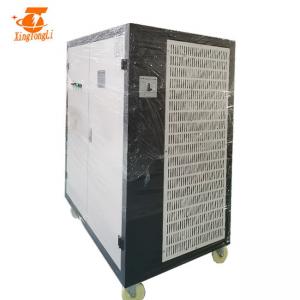
12V 10000A HF switch mode rectifier for copper electrolysis with water cooling
Switching power supply working principle:
The principle of voltage regulator switching power supply control regulator:
The switch knob repeatedly switches to a certain time interval. When the switch is turned on, the input power is supplied to the load through the switch knob and the filter circuit. During the entire switch is turned on, the power supply provides energy to the load;
When the switch is open, the input power is interrupted to provide energy. It can be seen that the input power supply for the load is intermittent. In order for the load to obtain continuous energy power, the switching power supply must have an energy storage device. When the switch is turned on, part of the energy is stored in the switch. The stored energy will be released to the load. The inductor is used for energy storage. When the switch is turned off, the energy in the energy storage inductor is released to the load through the diode to ensure that the load obtains continuous and stable energy. Because the diode allows the load to obtain continuous current, it is called a continuous current diode. This is how the switching power supply works.

Application
Different volt and current has different applications
Specification
| SPECIFICATIONS FOR GKD12-100 00CVC | |||
| Input AC | 380V±10% | 3phase | 50/60Hz |
| Output DC | Volt | 0~12V Adjustable | |
| Current | 0~10000A Adjustable | ||
| Power | 120KW | ||
| Efficiency | >85% | ||
| Switching Frequency | 20KHz | ||
| Protection | Short circuit protection Overheating protection Phase lack protection Input over/low voltage protection | ||
| Working Condition (Temperature) | -10℃~50℃ | Control mode | Panel control Remote control |
| Net weight | 80kg | Working mode | Constant Voltage(CV) Constant Current(CC) |
| Dimension(mm) | 480*600*740mm | Cooling way | Air cooling |
EAB in the average voltage between AB can be expressed as:
EAB=TON/T*E
TON wherein as each switch turn on time, T is the switching-off working cycle (ie, switch on-time TON and off-time TOFF together value).
By the equation, change the ratio of switch on-time and working cycle, the average voltage between AB also changed, therefore, as the load and input supply voltage changes automatically adjust the ratio of TON and T will cause the output voltage V0 remain unchanged. Changing the on-time working cycle TON proportions and that meanschanging the pulse duty cycle, this method is called as “time ratio control” (Time Ratio Control, abbreviated as TRC).
1. 0~10V, 4~20mA,PLC,Timer, Ampere-minute/hour counter, HMI can be provided
2. Control mode: Local control or Remote control(the length of cable is determined by customers)
3. Japan IGBT(the default choice) or Germany IGBT are adopted
4. After being phosphated, galvanized and plastic sprayed, the chassis has excellent corrosion resistence function
5. Easy to operate and repaire
Other advantages
1. Cabinet
a: Adopting completely digitalized machining
b: Adopting cold rolled production of iron steel sheet, after phosphorization, zinc plating, plastic spray, the rectifier gets better structural strength and anti-corrosion.
c: Reasonable structure design, isolated inverter design, rectification part is convenient to disassemble and mend because of its neat assembling.
d: Radiator gets better cooling effect because of its 1.5 times capacity.
2 Electric control system
a: The rectifier adopts full bridge phase-shifted soft switch control, ensuring the lowest power loss of IGBT. The capacity of IGBT become 3 times bigger.
b: The main transformer. It adopts amorphous core to increase transformer efficiency and cool transformer, and not only can lighten rectifier weight, but also can strengthen rectifier stability and reliability. At its elementary stage, it adopts series blocking capacitor.
c: Magnetic deviation automatic correction circuit is adopted and the total power of magnetic core gets enlarged 1.5 times.
3 Schottky Barrier Diode
a: It has been expanded 4 times.
4 All the controlling boards get antiseptic treatment with imported lacquer.
How to install rectifier
This is installation way for remote control rectifier. Not only this way.
1. To connect copper bar with bath/tank
2. To ensure power supply/rectifier is grounded
3. To ensure there is enough water for water cooling type power supply/rectifier
4. We advice that all rectifiers should be isolated to increase of its life.
Our service